Installation Guide
Requirements
The present documentation don’t attempt to guide the operator to install the printer. A certified Digitech Field Engineer or technician must perform the installation. Contact your local TruFire Service Deparment to schedule an installation service. Digitech has not responsability for injures or damage is caused by untrained personel. Also, the machine warranty may be void if the procedures are conducted out by unauthorized personnel.
Important
Before to install the printer the enginner must check if the customer meets all the requirements mentioned in the Site Preparation Guide.
Important
(PPE) Personal Protective Equipment must be wear while operating the printer.
Site of the printer
Check the floor.
Check power, air pipeline and network according to the Site Preparation.
Danger
High Voltage. Serious injuries or death may occur by untrained personnel. A certified electrician must connect the printer to the electrical panel.
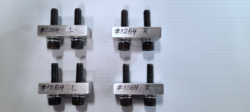
Removing the shipping brackets
Danger
HAND HAZARD Watch your fingers. Moving the gantry or headbox may cause injuries.
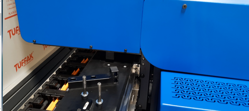
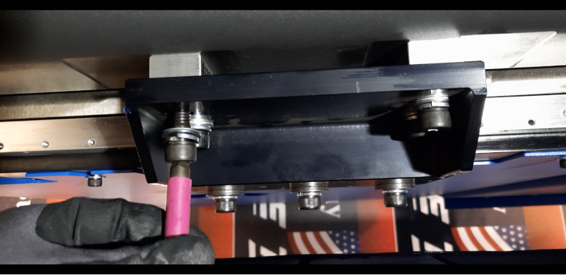
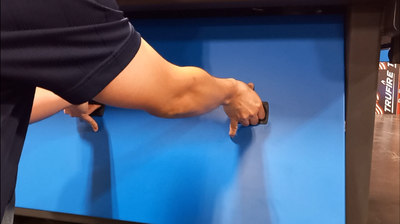
Remove the headbox shipping brackets. Loose the four socket head screws with a 6 mm allen wrench.
Check ‘How to remove the headbox shipping brackets’ [Video] for a full reference. xxxxxxxxxxxxxxxxxxxxxxxxx
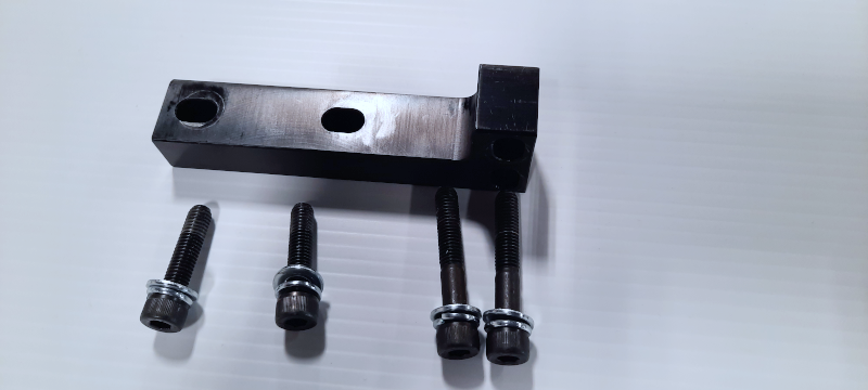
Remove the gantry shipping brackets from left side and right side. Loose the four socket head screws with a 8 mm allen wrench.
Check ‘How to remove the gantry shipping brackets’ [Video] for a full reference. xxxxxxxxxxxxxxxxxxxxxxxxx
Leveling the equipment
Caution
Heavy equipment
Position the gantry and the headbox on the middle of the table.
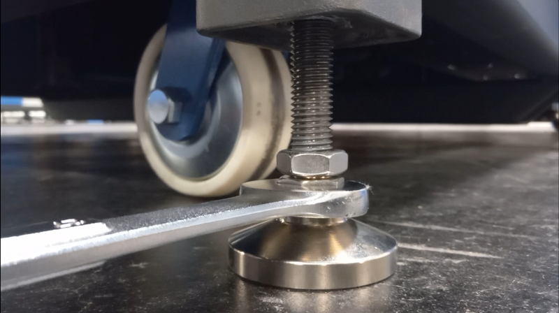
Unscrew the legs until touch the ground.
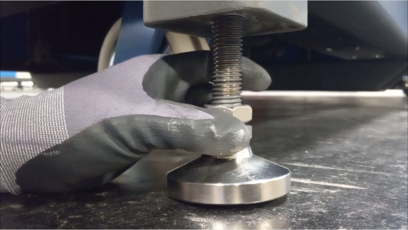
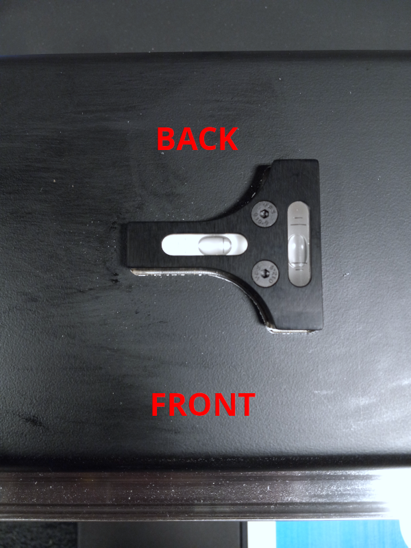
Level the printer using a torpedo level or use the built on levels located on the beam.
Start leveling the left side (front and back) repeat the procedure in the right side (front and back)
Check ‘How to leveling the printer’ [Video] for a full reference. xxxxxxxxxxxxxxxxxxxxxxxxx
Remove the covers to get access underneath the printer.
Check ‘How to remove the covers’ [Video] for a full reference. xxxxxxxxxxxxxxxxxxxxxxxxx
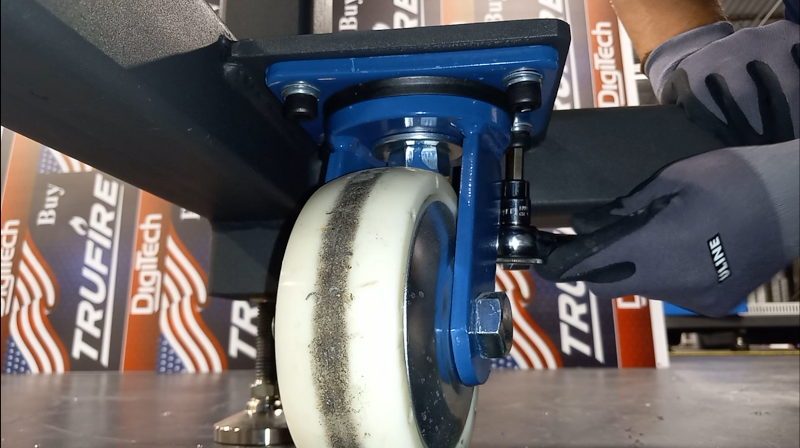
Remove the casters.
Check ‘How to remove the casters’ [Video] for a full reference. xxxxxxxxxxxxxxxxxxxxxxxxx
Installing the PPS Computer System
Important
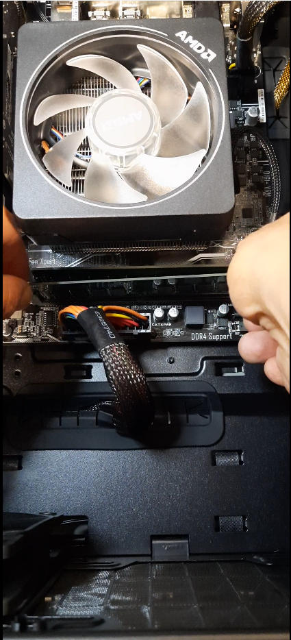
Reseed the RAM, video card and network card. While reseeding RAM memory requires you to apply moderate pressure. Note the position of the notches to align the RAM correctly, apply equal downward pressure on both sides and push it into the DIMM slot. Avoid excessive force or you may end damaging it. If both retaining clips don’t snap in, check if the RAM memory has been inserted in the correct direction.
Check ‘How to reseed the RAM, video card and network card’ [Video] for a full reference. xxxxxxxxxxxxxxxxxxxxxxxxxxxxxx
Place the computer in the front center cabinet.
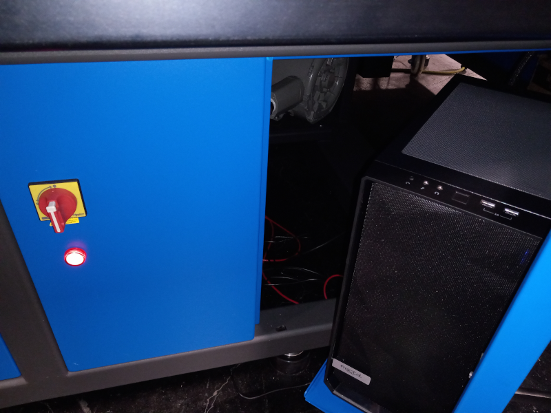
Mount the monitor in the stand.
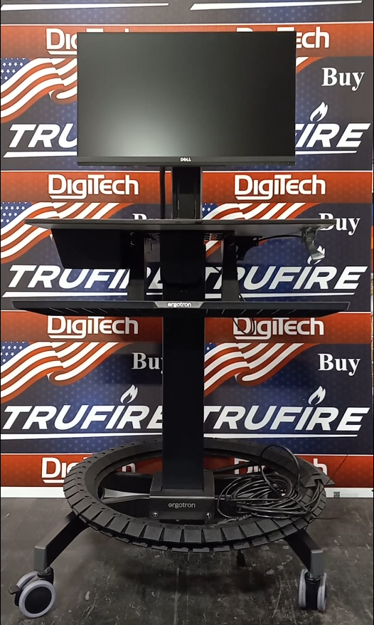
Connect the power cable, HDMI cable and USB cable.
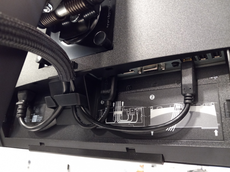
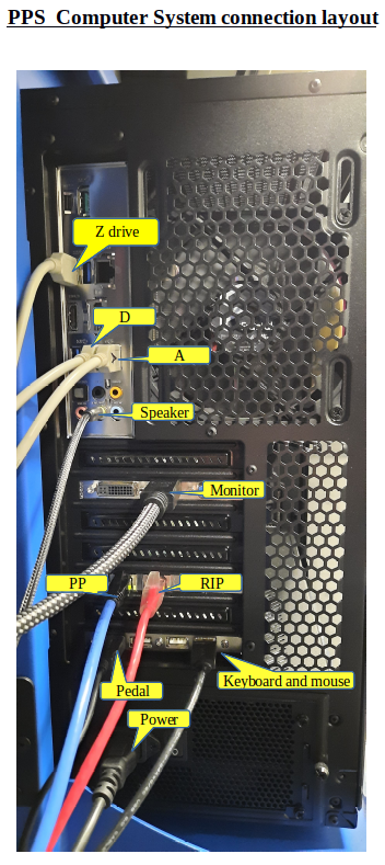
Important
Connect the cables to the PC according to the image below.
Checking electrical and network connections
Important
Inspection the unit for a loose wire or screw that might got loose during transportation.
A bad connection may cause malfunction.
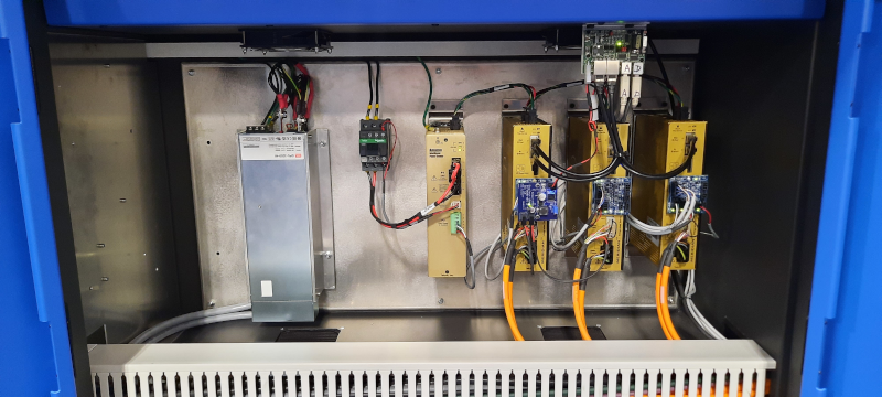
Left cabinet (printer with two blowers)
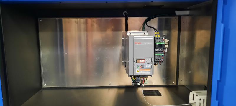
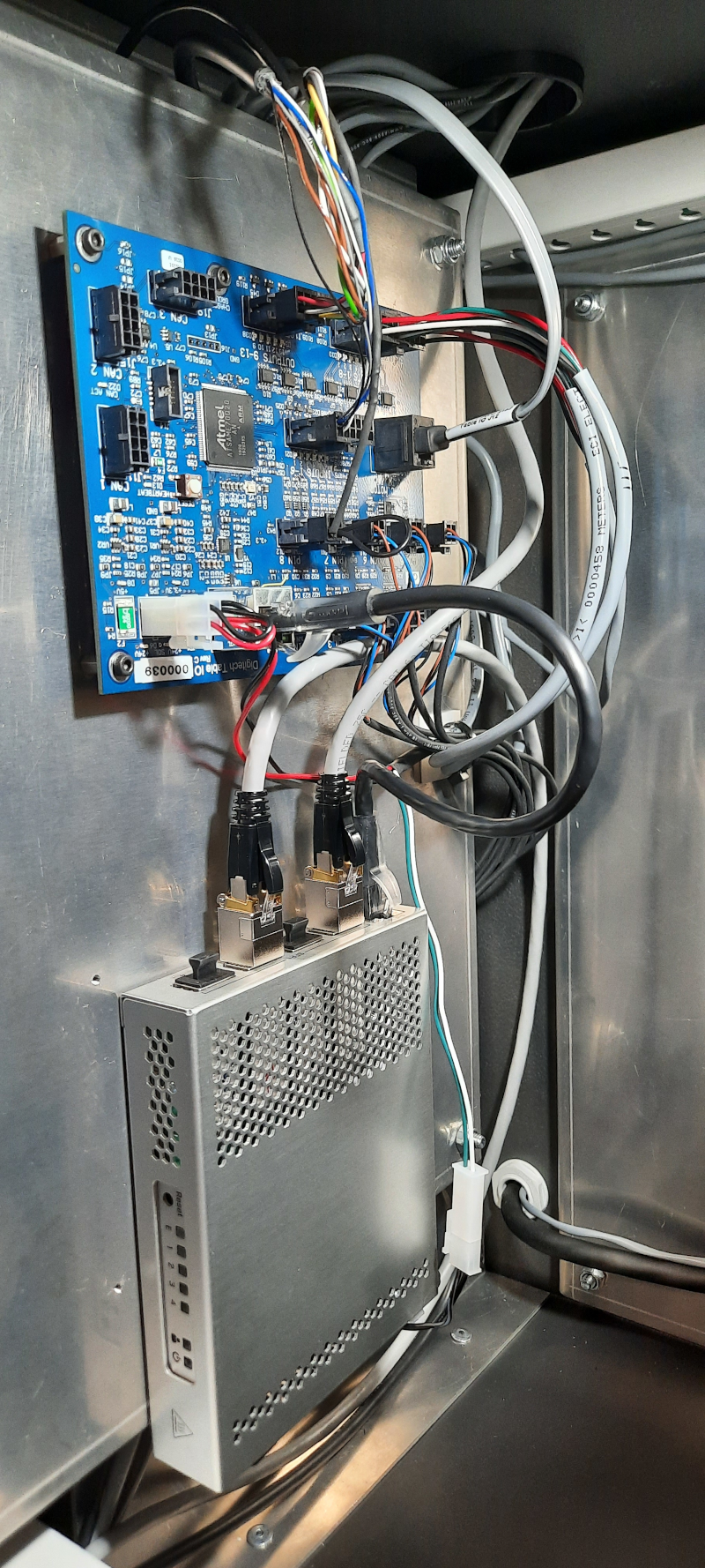
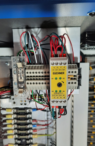
Center cabinet (TIO, Lower Switch. Vacuum controller, Emergency relay, 24 volts power supply and circuit braker)
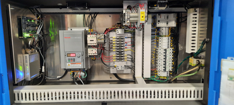
Right cabinet (uv power supply and motion system)
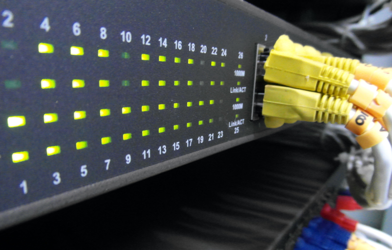
Reseed the network cables in the Switch, located inside the top headbox cover.
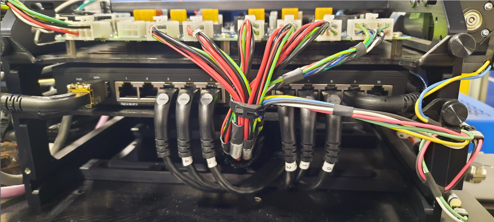
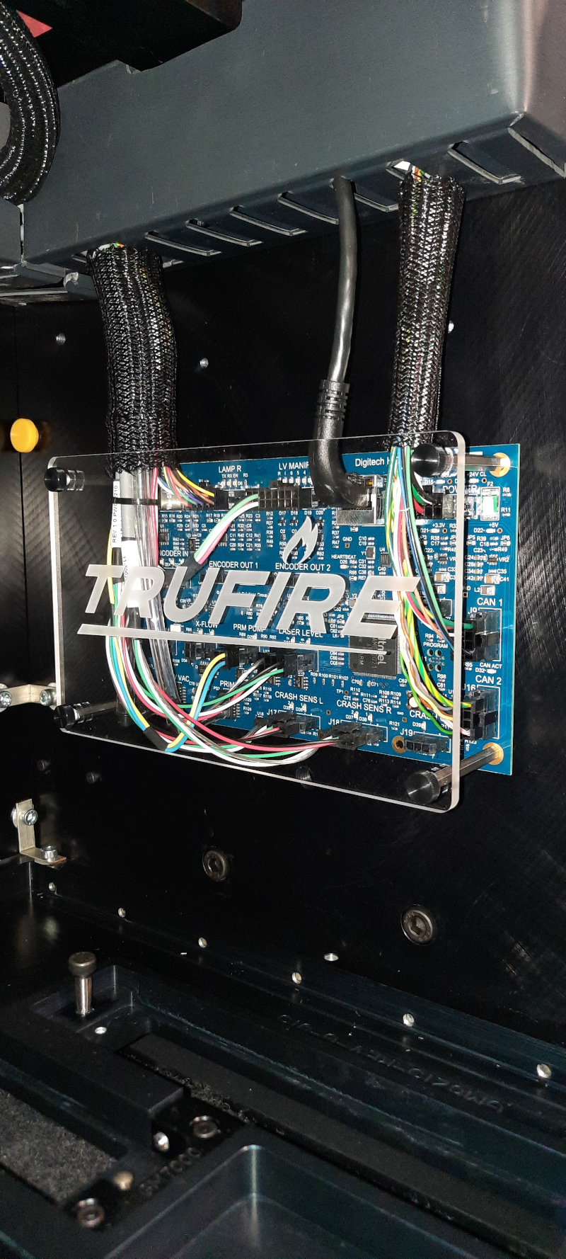
Reseed the network cables in the HIO board, located inside the front headbox cabinet.
Reseed the network cables in the TIO board and Lower switch, located on the back of the printer inside the central cabinet.
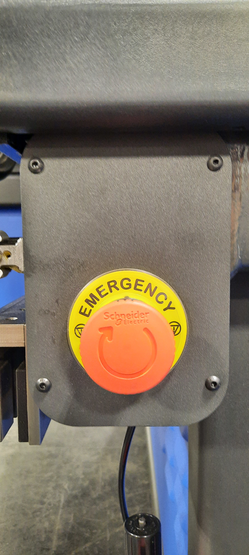
Mechanically reset the emergency stop buttons.
Power up the printer
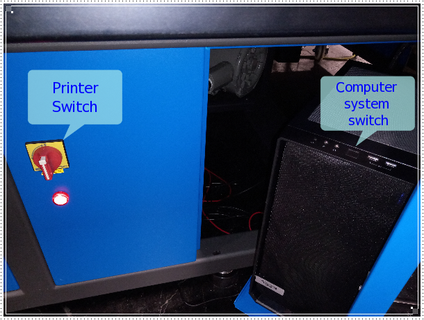
Turn on the main switch.
Turn on the computer system.
Important
Wait 2 minutes for the printer network systems initialization.
Check the status of the emergency stop relay (four LED on)
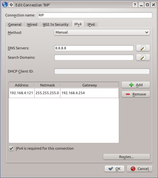
Configuring the Internet Access
Important
A dedicated IP address is recomended to avoid IP conflicts.
Open the network editor
Edit the IP adreess, netmask, gateway and DNS according to the ISP or intranet configuration.
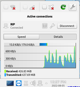
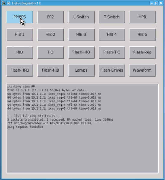
Testing Network Connectivity
Run the TruFire Diagnostics desktop application to check the printer network systems connectivity.
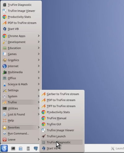
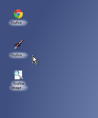
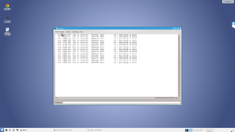
Printer Initialization
Run TruFire Launch from desktop.
Note
Follow the Daily Start Up and the GUI Guide instructions
Installling the printheads
Important
FRAGILE. Electronic device, do not drop or scratch the printhead surface. Handle with care
Remove the print head capping.
Put the head screw on the back of the printhead
Mount the printhead into the first left slot on the printhead plate
Put the head screw on the front of the printhead
Check the printhead placing on the slot
Check ‘How to install the printeheads’ [Video] for a full reference. xxxxxxxxxxxxxxxxxxxxxxxxxxxxxx
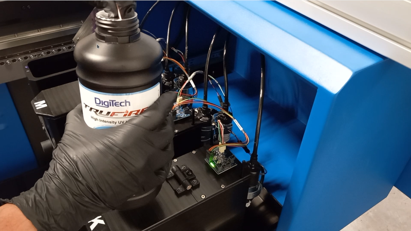
Filling up the ink buckets
Important
Only use the inks and flush cleaning solution / head surface cleaner recommended by Digitech.
KSJ-C1 Cyan
KSJ-M1 Magenta
KSJ-Y1 Yelow
KSJ-K1 Black
KSJ-FL1 Flush and Head Surface Cleaner

Open the ink bucket cabinet located on the right back gantry, pull the tray and fill up the ink on each bucket according to its label.
Check ‘How to Filling up the ink buckets’ [Video] for a full reference. xxxxxxxxxxxxxxxxxxxxxxxxxxxxxx
Crossflow the printheads
Caution
(PPE) Wear Safety Glasses
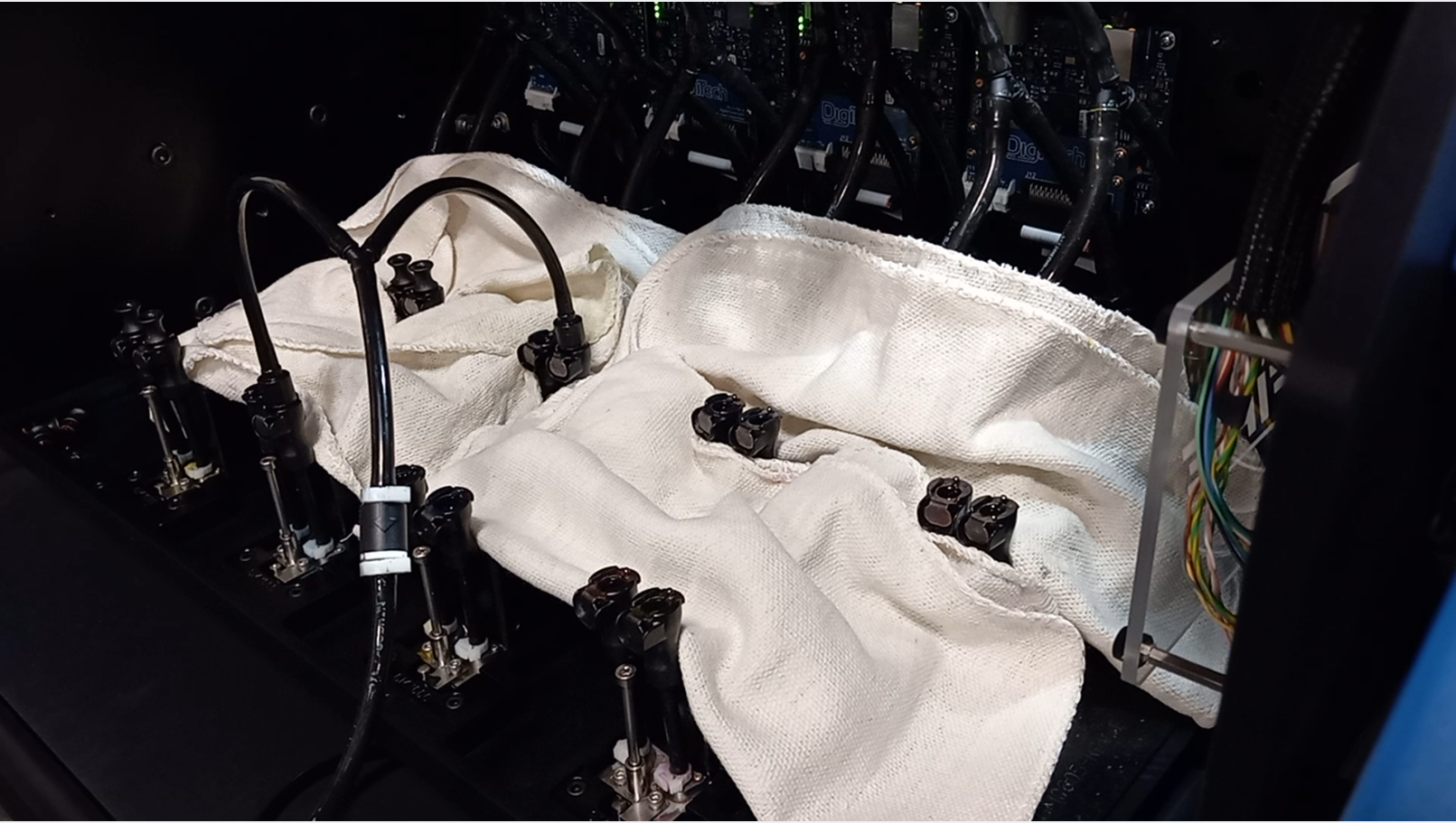
Prepare the printheads to crossflow. Protection the ribbon and power cable from ink spills.
Check ‘How to prepare the printheads for a crossflow’ [Video] for a full reference. xxxxxxxxxxxxxxxxxxxxxxxxxxxxxx
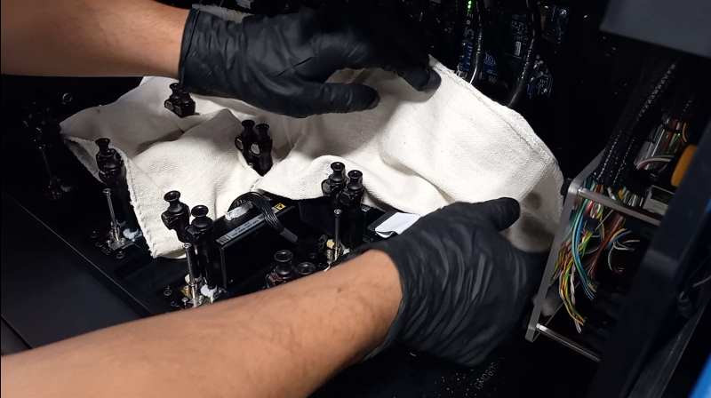
Plug in the crossflow kit into the printhead fast connection fitting. Make sure the clip snap. ex. Left yellow back row and left yellow front row.
Check ‘How to plug in the crossflow kit to the printhead’ [Video] for a full reference. xxxxxxxxxxxxxxxxxxxxxxxxxxxxxx
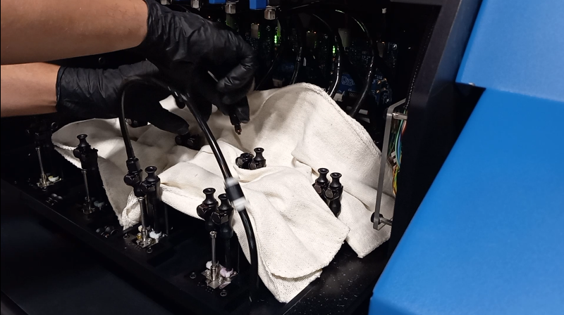
Prime 2 seconds, wait for the reservoirs to filling up then repeat the procedure twice for each printhead.
Check ‘How crossflow the printheads’ [Video] for a full reference. xxxxxxxxxxxxxxxxxxxxxxxxxxxxxx